In any software programming language, when we need to deal with a collection of elements of the same type we can take advantage of the dedicated data structures provided by the language. In VHDL such kind of structure is defined “array“.
We can collect any data type object in an array type, many of the predefined VHDL data types are defined as an array of a basic data type.
type string is array (positive range <>) of character; type bit_vector is array (natural range <>) of bit;
The VHDL Arrays can be may both one-dimensional (with one index) or multidimensional (with two or more indices).
When we declare an array, we can decide if the array is
In the constrained array, he bounds for an index are established when the array type is defined
In the unconstrained array, the bounds are established subsequently during the declaration of the variable or signal.
The BNF for declaring an array type is:
array_type_definition ::= unconstrained_array_definition | constrained_array_definition unconstrained_array_definition ::= array ( index_subtype_definition < , index_subtype_definition >) of element_subtype_indication constrained_array_definition ::= array index_constraint of element_subtype_indication index_subtype_definition ::= type_mark range <> index_constraint ::= ( discrete_range < , discrete_range >) discrete_range ::= discrete_subtype_indication | range subtype_declaration ::= subtype identifier is subtype_indication ; subtype_indication ::= [ resolution_function_name ] type_mark [ constraint ] type_mark ::= type_name | subtype_name constraint ::= range_constraint | index_constraint
the subtype allows the values taken on by an object to be restricted or constrained subset of some base type.
Some examples of constrained array type declarations:
type t_vector is array (integer range <>) of real; type t_word is array (31 downto 0) of bit; type t_memory is array (address) of word; type t_transform is array (1 to 4, 1 to 4) of real; type string is array (positive range <>) of character; type bit_vector is array (natural range <>) of bit; signal mystring : string(1 to 255); variable mybitvector : bit_vector(15 downto 0);
An element of an array object can be referred to by indexing the name of the object.
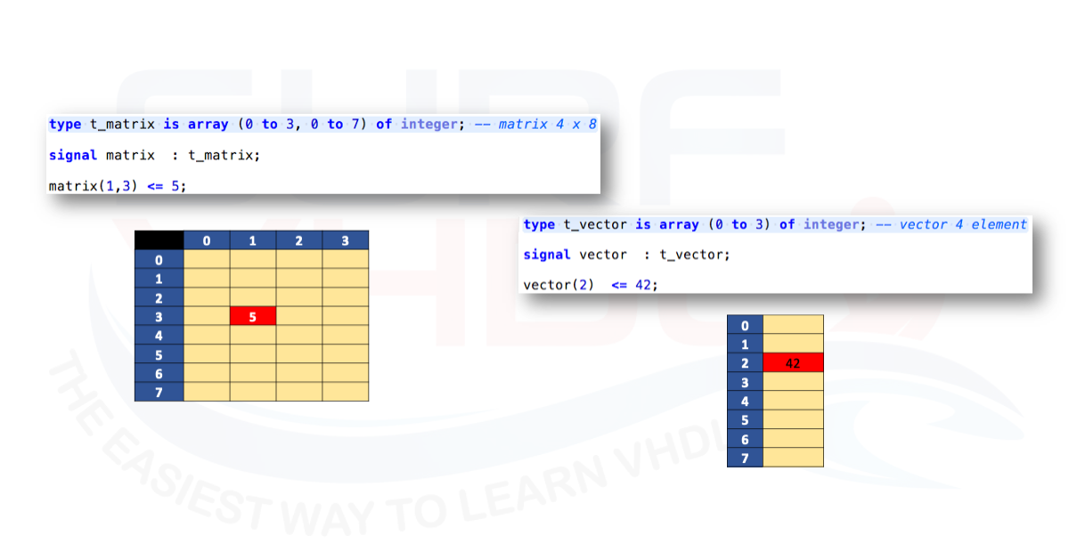
Figure 1 reports an example of the signal vector and matrix addressing, here below the VHDL code for matrix and vector definition and addressing.
type t_matrix is array (0 to 3, 0 to 7) of integer; -- matrix 4 x 8 type t_vector is array (0 to 3) of integer; -- vector 4 element signal matrix : t_matrix; signal vector : t_vector; matrix(0,2)Implementing a MUX using an array in VHDL
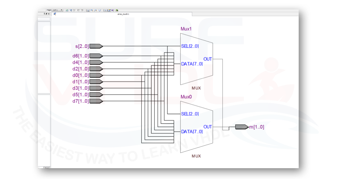
In this post, we describe the VHDL implementation of a MUX using the CASE-WHEN statement. Another compact and elegant way for describing a MUX architecture in VHDL is to use the array approach. In the VHDL code below is reported the VHDL code of the implementation of an 8-way MUX. We defined an array of the same type of data of the MUX then the array is referenced using the MUX selector. In a single VHDL line, we can implement an N-way MUX.
library ieee ; use ieee.std_logic_1164.all; use ieee.numeric_std.all; entity array_mux8 is port( d0 : in std_logic_vector(1 downto 0); d1 : in std_logic_vector(1 downto 0); d2 : in std_logic_vector(1 downto 0); d3 : in std_logic_vector(1 downto 0); d4 : in std_logic_vector(1 downto 0); d5 : in std_logic_vector(1 downto 0); d6 : in std_logic_vector(1 downto 0); d7 : in std_logic_vector(1 downto 0); s : in std_logic_vector(2 downto 0); m : out std_logic_vector(1 downto 0)); end array_mux8; architecture rtl of array_mux8 is type t_array_mux is array (0 to 7) of std_logic_vector(1 downto 0); signal array_mux : t_array_mux; begin array_mux(0)As example, Figure 2 shows the RTL view of the 8-way MUX implementation on Altera/Intel Cyclone II FPGA
Implementing a LUT using an array in VHDL
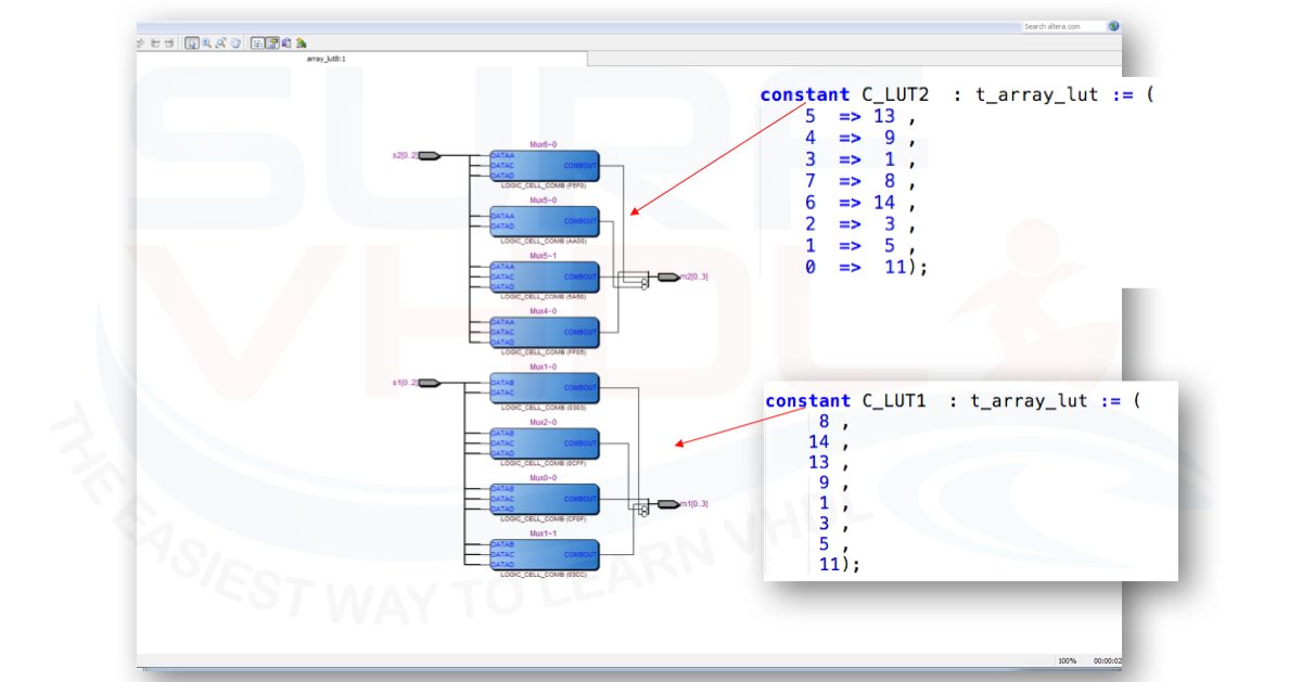
A typical application of array in VHDL is the implementation of a LUT aka Look Up Table. In the example below is reported a vector of integer whose range is 0 to 15 i.e. 4 bit unsigned. The LUT is can be initialized in different ways as in the VHDL example below:
library ieee ; use ieee.std_logic_1164.all; use ieee.numeric_std.all; entity array_lut8 is port( s1 : in std_logic_vector(2 downto 0); s2 : in std_logic_vector(2 downto 0); m1 : out std_logic_vector(3 downto 0); m2 : out std_logic_vector(3 downto 0)); end array_lut8; architecture rtl of array_lut8 is type t_array_lut is array (0 to 7) of integer range 0 to 15; constant C_LUT1 : t_array_lut := ( 8 , 14 , 13 , 9 , 1 , 3 , 5 , 11); constant C_LUT2 : t_array_lut := ( 5 => 13 , 4 => 9 , 3 => 1 , 7 => 8 , 6 => 14 , 2 => 3 , 1 => 5 , 0 => 11); begin m1Figure 3 shows the technology view of the LUT implementation on Altera/Intel Cyclone II FPGA
Implementing a Digital Signal Processing section using an array
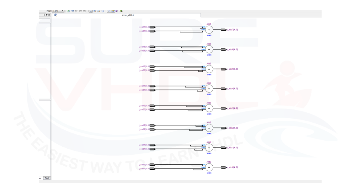
Another typical example of array usage is when you need to perform the same operation on a large number of a signal. An example is adding two sets of input number in the code below:
library ieee ; use ieee.std_logic_1164.all; use ieee.numeric_std.all; entity array_add8 is port( -- first set op openrand i_op10 : in std_logic_vector(3 downto 0); i_op11 : in std_logic_vector(3 downto 0); i_op12 : in std_logic_vector(3 downto 0); i_op13 : in std_logic_vector(3 downto 0); i_op14 : in std_logic_vector(3 downto 0); i_op15 : in std_logic_vector(3 downto 0); i_op16 : in std_logic_vector(3 downto 0); i_op17 : in std_logic_vector(3 downto 0); -- second set op openrand i_op20 : in std_logic_vector(3 downto 0); i_op21 : in std_logic_vector(3 downto 0); i_op22 : in std_logic_vector(3 downto 0); i_op23 : in std_logic_vector(3 downto 0); i_op24 : in std_logic_vector(3 downto 0); i_op25 : in std_logic_vector(3 downto 0); i_op26 : in std_logic_vector(3 downto 0); i_op27 : in std_logic_vector(3 downto 0); -- output o_add0 : out std_logic_vector(4 downto 0); o_add1 : out std_logic_vector(4 downto 0); o_add2 : out std_logic_vector(4 downto 0); o_add3 : out std_logic_vector(4 downto 0); o_add4 : out std_logic_vector(4 downto 0); o_add5 : out std_logic_vector(4 downto 0); o_add6 : out std_logic_vector(4 downto 0); o_add7 : out std_logic_vector(4 downto 0)); end array_add8; architecture rtl of array_add8 is type t_array_op is array (0 to 7) of signed(4 downto 0); signal w_op1 : t_array_op; signal w_op2 : t_array_op; signal w_add : t_array_op; begin w_op1(0)Figure 4 shows the RTL view of the 8-adder implementation on Altera/Intel Cyclone II FPGA using the array approach.
Conclusion
As you saw in the previous example, using array allow you writing a very compact and elegant VHDL code. Moreover, using array approach you minimize the coding error since the VHDL code is more compact and simple to read and understand. After all these advantages, you should pay a great attention to your VHDL. Using the array coding style, you can fill a huge FPGA with only just few line of VHDL code! The rule is always the same:
Every time you write a VHDL code, check the area report if it matches with your design intention and when you are not sure of the VHDL synthesis, check the RTL viewer and technology view.
Reference
[1] RTL HARDWARE DESIGN USING VHDL Coding for Efficiency, Portability, and Scalability
[2] VHDL Programming by Example 4th Ed Douglas – Perry